Fast PWM-DAC library for the SAMD21
This library is an improvement of the standard Arduino function analogWrite(). The analogRead() is also made much faster, see this article: Fast analogRead / 10-bit ADC for the Arduino Uno and Zero.
The library is essentially a wrapper around the Adafruit_ZeroTimer.
Todo
This library should be integrated in the library: https://avdweb.nl/arduino/adc-dac/fast-pwm-dac
Download
Download the library from GitHub, you will find here program examples too.
These libraries should be installed also:
Advantages of the fast PWM-DAC
- The PWM frequency is much higher.
- The resolution can be set.
- The timer number can be set.
Using the PWM-DAC
The library is easy to use; the following code creates a 10bit DAC on pin 5 of the Arduino Zero and sets output to 1.65V:
#include <avdweb_SAMDpwmDAC.h>
SAMDpwmDAC myDAC = SAMDpwmDAC(3, 10, 5);
myDAC.write(512); // 512/1024 * 3.3V = 1.65V
Explanation:
- myDAC: this is the object name of you choice.
- 3: take any free timer.
- 10: the resolution in bit.
- 5: output pin 5. Two pins can be used: D5 and D12; see the pin-table.
Notes
- For now, the library has three timers available (number 3, 4, 5)
- The timers are used in 16-bit mode.
- There is no check on the proper parameters values.
High PWM frequency
Due to the higher PWM frequency, the RC low-pass filter has a shorter settling time. The PWM frequency depends on the resolution. We can calculate the PWM frequency as follows:
PWM frequency = 48MHz / 2^resoluton
For example, for a resolution of 10bit, the PWM frequency is 47kHz. Note that with analogWrite, at the same resolution, the frequency is just 732Hz.
RC low-pass filter design
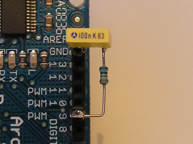
Suppose that the RC low-pass filter has an allowed ripple of 0.1% at 1.65V output voltage. The PWM-DAC resolution is 10bit, so the frequency is 47kHz. With this online tool we can calculate the low-pass filter:
This RC filter is obtained by using the online tool:
- f = 47kHz
- R = 68kΩ
- C = 150nF
- Settling time 0% ... 90% = 23ms
There is only needed a small RC filter at the high-speed DAC:

For analogWrite(), the settling time is much longer:
- f = 732Hz
- R = 68kΩ
- C = 10uF
- Settling time 0% ... 90% = 1.56s
Setting the resolution
The library is straightforward since the resolution is set during initialisation. We can set any resolution from 1 ... 16bit, although a resolution of 1 ... 7bit is of little use.
With analogWrite(), the resolution has to be set first with analogWriteResolution(), so this requires two steps. This resolution than will remain the same for the rest of the program. In program technical point of view, this is an undesirable situation. How do we know the resolution at any moment?
Setting the timer number
The SAMD21 has 6 timers, so we can use maximal 6 different PWM DACs at the same time. To organise this, it is useful that the timer number can be set, so there is no doubt about it. This table can be used to determine which pins are available for each timer:
 SAM15x15 and Arduino Zero Timer/Counter pins
As you can see, the distribution of pins is rather messy.
The disadvantage of analogWrite() is that we don't know the timer number at initialisation:
analogWrite(pin, value);
That makes it harder to find out how many PWM DACs are left and which pins are free.
Future improvements
The timers 0, 1 and 2 are not implemented yet. I hope that other people want to do this on GitHub.

