Arduino Fast Code Debug Oscilloscope Library
- Eliminating the disruption of the program by the serial monitor while debugging
- When should you use the Arduino Code Debug Oscilloscope Library?
- How does it work?
- Example
- Code on GitHub
- Use as a common oscilloscope
- Features of the Code Debug Oscilloscope
- Similar commercial products
- Difference with normal oscilloscope
- Operation of the Code Debug Oscilloscope
- Fast 10-bit ADC
- Example with two channels and pre-trigger
- Serial port output:
- Example with interrupt service routine
- Serial port output:
- Circular buffer size
- Other Arduino fast oscilloscopes
Eliminating the disruption of the program by the serial monitor while debugging
Normally, you can easily debug your Arduino sketch with the serial monitor, but this is not always possible, as the serial monitor disrupts the progress of the program. That's why I developed the Code Debug Oscilloscope, it has helped me with a lot with complex projects.
 Arduino Code Debug Oscilloscope
When should you use the Arduino Code Debug Oscilloscope Library?
- When conventional debugging via the serial monitor isn't feasible.
- When the data is too fast for the serial monitor.
- When oscilloscope functionality is required.
How does it work?
The Code Debug Oscilloscope is in fact a circular buffer with oscilloscope functions. During debugging, the data to be checked is stored in a buffer. After debugging, the data in the buffer will be sent to the serial monitor and can eventually be shown in a graph by Excel. The library has been kept as simple as possible to save memory space and optimize the speed.
Example
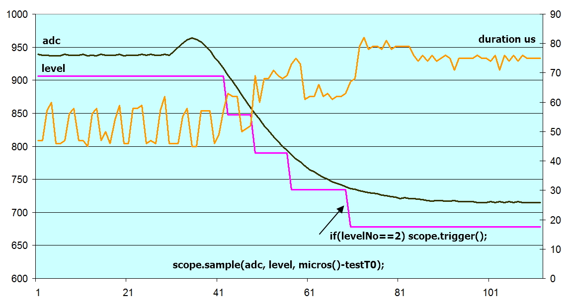
Because the Code Debug Oscilloscope can measure all internal variables, complicated tests can be done:
 Arduino High Speed Visual Debugging Tool
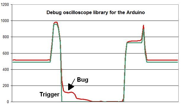
With the help of the trigger() we can catch very hard to find bugs:
 Arduino High Speed Visual Debugging Tool
Code on GitHub
Download the library from GitHub.
I want to thank Abhijit Bose, he now manages the library and is making further improvements.

Bengaluru, Karnataka, Bharat(India)
Entrepreneur with an electronics engineer's heart, and passion for Soldering, Firmware, Open-source and Mindfulness. Trying to maximize - happiness, satisfaction, peace and privacy through technology for everyone.
The library will be improved further:
- Set the buffer size via the constructor.
- Keep the serial print part outside the library.
- Warnings if something is done wrong.
Use as a common oscilloscope
Of course, it is possible to use the ADC for measuring external signals, just like a normal oscilloscope.
Features of the Code Debug Oscilloscope
- Measuring all kinds of sketch-variables, with or without analog input values.
- Suitable for ATmega328 and SAMD21 Arduino boards: Arduino Uno, Arduino Zero, SAM 15x15, etc.
- The trigger signal can be generated by the sketch.
- It can be used for 1, 2, 3 or 4 channels.
- It has pre-trigger and post-trigger.
- The sample rate is measured and printed.
Similar commercial products
Difference with normal oscilloscope
An Arduino has an inside world and outside world. With an oscilloscope we can measure the outside world. However, everything what happens inside remain hidden. To debug complex sketches, it would be nice if we could measure electronic signals outside the board together with internal sketch-variables. So, I have built this Code Debug Oscilloscope, which is an extreme powerful tool for debugging.
Operation of the Code Debug Oscilloscope
Start
Specify the number of channels and start: scope.start(2); (for 2 channels)
The scope waits for the trigger: scope.trigger();
After the trigger, the scope records the samples.
probeAB(...); (inside a loop, for 2 channels)
Trigger
We have to give a trigger() or stop() signal, else nothing happens.
When more triggers are given, only the first trigger is taken.
Print to the serial monitor
Use showIfReady() to print the recorded values.
RecordLenght
The record length, this is the same as the circular buffer size, depends on the number of channels and the kind of processor that is used. For the SAMD21G18 on the Arduino Zero, the size is set to 2000 bytes. Since the samples are short integers (2 bytes), this results in maximum 1000 samples for the SAMD21G18. For 2 channels, these are respectively 500 samples.
A large buffer size can have the disadvantage that it may take too much time until all samples have been taken. Therefore, you can specify a smaller buffer size, for example:
scope.start(2, 0, 50); (2 channels, record length 25 samples (50/2) instead of 1000)
Stopping immediately
Instead of waiting until the scope is ready, we can also abort sampling and show the values immediately at the serial monitor. This is done with the stop signal:
stop();
The stop works also when no trigger was given before.
Pre trigger
Optionally, the number of pre samples can be specified, for example:
scope.start(1, 20, 100); (1 channel, pre samples = 20, record length = 100)
Post trigger
The number of post samples may be specified with a negative value, for example:
scope.start(1, -10, 100); (1 channel, post samples = 10, record length = 100)
Fast 10-bit ADC
As part of the Code Debug Oscilloscope library, I have developed a fast 10-bit ADC, the maximum sample rate with one analog input is 50kS/s..
Example with two channels and pre-trigger
#include "avdweb_SWscope.h" // https://avdweb.nl/arduino/measurement/oscilloscope

// Attention: set in avdweb_SWscope.h: const int maxScopeBytes = 100; // or more if possible

SWscope scope;

void setup(void)
{ Serial.begin(115200);
  scope.start(2, 10); // 2 integer channels , preSamples = 10, buffer is 100/4=25 integer values
  // scope.testBuffer(); // print 100/2 = 50 integer values with only channel A
}

void loop(void)
{ static int internalValue;
  internalValue += 2;
  scope.probeAB(internalValue, analogRead(A0)); // channel A = internalValue, channel B = ADC
  if(internalValue > 10) scope.trigger();
  scope.showIfReady();
}
Serial port output:
usPerDiv: 113
ptr, values
21 0 0
22 0 0
23 0 0
24 0 0
0 2 106
1 4 80
2 6 62
3 8 47
4 10 36
5 12 28
6 14 21 trigger
7 16 16
8 18 12
9 20 9
10 22 7
11 24 5
12 26 3
13 28 2
14 30 1
15 32 0
16 34 0
17 36 0
18 38 0
19 40 0
20 42 0
Example with interrupt service routine
#include "avdweb_SWscope.h"
#include <FrequencyTimer2.h> // mainISR https://github.com/PaulStoffregen/FrequencyTimer2

// Attention: set in avdweb_SWscope.h: const int maxScopeBytes = 100; // or more if possible

SWscope scope;

void setup(void)
{ Serial.begin(115200);
  FrequencyTimer2::setPeriod(250); // period = 250us
  FrequencyTimer2::setOnOverflow(mainISR); // start ISR here
  scope.start(2, 10); // 2 integer channels , preSamples = 10, buffer is 100/4=25 integer values
  scope.trigger();
}

void mainISR(void)
{ static int internalValue;
  internalValue += 2;
  scope.probeAB(internalValue, analogRead(A0)); // channel A = internalValue, channel B = ADC
  if(internalValue > 10) scope.trigger();
}

void loop(void)
{ scope.showIfReady();
}
Serial port output:
usPerDiv: 120
ptr, values
15 0 0
16 0 0
17 0 0
18 0 0
19 0 0
20 0 0
21 0 0
22 0 0
23 0 0
24 0 0
0 2 75 trigger
1 4 53
2 6 37
3 8 25
4 10 16
5 12 10
6 14 5
7 16 2
8 18 0
9 20 0
10 22 0
11 24 0
12 26 0
13 28 0
14 30 0
Create charts with the Serial Plotter Tool
The most convenient way to visualize the data is using the the Serial Plotter Tool.
Create charts with Excel
Copy the data from the serial port window and paste it to Excel with "paste special".
Circular buffer size
The maximum circular buffer size is about
- ATmega328 used in the Arduino Uno: 700 bytes
- SAMD21 used in the Arduino Zero: 7000 bytes
If the Code Debug Oscilloscope library is part of a large sketch, the circular buffer would have to reduced, do this by changing maxBytes in the library header file.
If the buffer is made too large then we get an uncontrolled situation. While there are no compiler errors, the content at the end of the circular buffer may be overwritten by nonsense. The reason is that the Arduino works without operating system that keeps control.
Other Arduino fast oscilloscopes
Here are similar Arduino programs, but they are not libraries:

