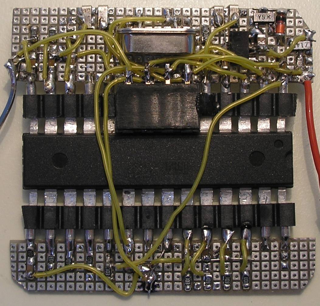
Old ebike cycle computer
This article is about an old design from 2013, it is being replaced by the E-kit.
Intro
Here I describe briefly the first cycle computer that I have built for the Maxun One solar bike, it is the OLD version.
The LCD shows what is measured:

If the measuring range is exceeded, an exclamation point is displayed, V! or A!.
Serial output for data logging
All values are sent to the USB port too, so you can connect a laptop for data logging.
Serial output:
23 kmh 38.30 V 6.27 A 240 W
23 kmh 38.40 V 6.28 A 241 W
Circuit Arduino ebike cycle computer
 Arduino ebike cycle computer 2013
 Arduino ebike cycle computer KU63 part 2013
Standalone Arduino
If the serial output is not needed, we can simply use a Standalone Arduino:
Voltage measurement
The voltage is measured with the ATmega328 10bit ADC. We can apply a simple voltage divider to measure the entire battery voltage range of 0V to 44V. However, this causes a poor resolution of the interesting voltage range between 39V and 44V. Therefore, I use an amplifier with two rail-to-rail op-amps LMC6484IN that convert the range 29V ... 44V into 0 ... 5V.
Current measurement
To measure the motor current, I recommend to use a Hall effect current sensor, such as the ACS712.
For the current measurement, I created a shunt of constantan wire. The value is 2mΩ, the power loss just 0.2W at a current of 10A. The width is 7.5mm.
First, I have bent a copper wire into a U shape and then wrapped the constantan wire around it. After soldering, I have cut away the short circuit at the top.
Because the shunt amplifier has a gain of 100, the op-amp offset plays a major role. This offset can be eliminated by the software easily. To make this possible the op-amp circuit adds an offset voltage of 3mV, otherwise negative op-amp offset can't be measured and corrected.
Using the motor controller shunt
It is possible to use the built-in motor controller shunt. Here is a circuit for the KU63 motor controller, which has a shunt of 5mΩ.
 Using the motor controller shunt
Speed measurement
A wheel magnet of a bicycle computer is used to measure the speed. Alternatively, a Hall-sensor can be used (5V, Hall out, gnd). I used my Frequency / period counter library to measure the period time of the wheel magnet pulses. The speed is calculated by
speed [kmh] = 3600 * wheelCircumference [m] / period [ms]
Distance measurement
This is not implemented yet, try the following code (not tested):
unsigned long revolutions=0;
void wheelSR()
{ wheelSpeed.poll();
revolutions++;
}
In displayLCDandScreen()
pString << (float) revolutions * wheelCircumference / 1000 << " km\n";
Liquid crystal display
Each LCD can be used if there is a suitable Arduino library available. I used the 5110 LCD module, see my article How to use the Nokia 5110 LCD Module at Arduino.
Software
Not all the code is public.
|
#include <PCD8544.h>
#include <Streaming.h>
#include <PString.h>
#include <FreqPeriodCounter.h>
#include <Albert.h>
#include "WattMeter.h"
// PINS
const byte Upin = 0;
const byte Ipin = 1;
const byte wheelSpeedPin = 2;
const byte wheelInterrupt = 0; // = pin 2
// DEFINITIONS
#define wheelCircumference 2.16
#define debounceTime_ms 1 // pulse > 3ms
#define msPerSec 1023 // calibration for ATtiny
#define numberOfMagnetsPerWheel 1
#define wheelTimeOut_ms 2000
#define PiezoBuzzerFreq 2400
#define LCDupdate_ms 500
#define LCDmaxChar 100
// Compile time calculations
const float k = (float)3600 * wheelCircumference / numberOfMagnetsPerWheel; // kmh = k / period
char LCDbuffer[LCDmaxChar];
PString pString(LCDbuffer, sizeof(LCDbuffer));
PCD8544 lcd = PCD8544(10, 11, 12); // 3 pin LCD control, SCLK, DN, D/C
FreqPeriodCounter wheelSpeed(wheelSpeedPin, millis, debounceTime_ms);
WattMeter wattMeter;
void setup(void)
{ Serial.begin(9600);
lcd.init(49); // contrast
lcd.clear();
attachInterrupt(wheelInterrupt, wheelISR, CHANGE);
}
void loop(void)
{ static unsigned long lastLCDms;
wattMeter.movingAverage();
if(millis() - lastLCDms > LCDupdate_ms)
{ lastLCDms = millis();
wheelSpeed.poll();
displayLCDandScreen();
}
}
void wheelISR()
{ wheelSpeed.poll();
}
|
Voltage calibration
The E-bike Watt meter must first be calibrated. The voltage is calculated from the ADC value with the formula:
U = aU * adc + bU. The correct values of aU and bU are determined by the calibration.
- First, change the values in de software temporary: aU = 1 and bU = 0.
- Use a digital multimeter to calibrate the voltage measurement. Connect a variable voltage from 29V to 44V to the E-bike Watt meter and enter the measured values and the LCD values into Excel.
- Create a chart in Excel. Use the trend line option to display the formula.
- The values aU and bU can simple be read from the formula: aU = -0.0146 and bU = 43.976. Change these values in de software.
 E-bike-Watt-meter-calibration Excel sheet
Current calibration
The procedure is similar to the calibration of the voltage, just change the values aI and bI. Calibrate with a variable current of 0 to about 10A.
Speed calibration
Measure accurately the wheel circumference of the bike under load, so you have to sit on it. Enter the measured value in the software at
#define wheelCircumference


