Old spot welder controller smd v5
- Wiring and mounting
- Weld times
- Heatsink
- Interval time
- Practical welding examples
- Controlling high-power spot-welding machines
- Built-in power supply
- How to customize weld times
- Microwave oven repair safety precautions
- Questions
- Circuit description
- Zero crossing detector circuit
- High voltage!
- Maximum thyristor current
- Alternistors for high inductive loads
- User guide
- More information
For the new version see HERE
I have developed the D.I.Y spot welder because I needed a special spot welder for the building of my Maxun One solar bike. It turned out that the spot welder is being built by many people worldwide.
This spot-welder timer controller is completely ready:
- Including the TFT display
- Including the 110VAC ... 240VAC mini power supply
- Completely assembled
- Programmed with the Arduino bootloader and the spotwelder code
- Fully tested
- Ready for use
You can use it for:
- DIY spot welder made with a microwave oven transformer
- Improving the Harbor Freight / Kende Welding Machine DN-100E (with the high power controller)
- For the repairing the Sunkko 788 welder
 Spot welder control board with TFT display
Attention
There are cheap spot welders timers for sale on eBay. These are pretty good, but they do not have a zero crossing detector circuit. This is necessary for the reduction of the weld transformer inrush current, to prevent the mains fuse blow up.
Menu controlled operation with TFT display
The big advantage of this spot-welder timer is that the control is menu-driven and therefore very simple. A manual is actually unnecessary.
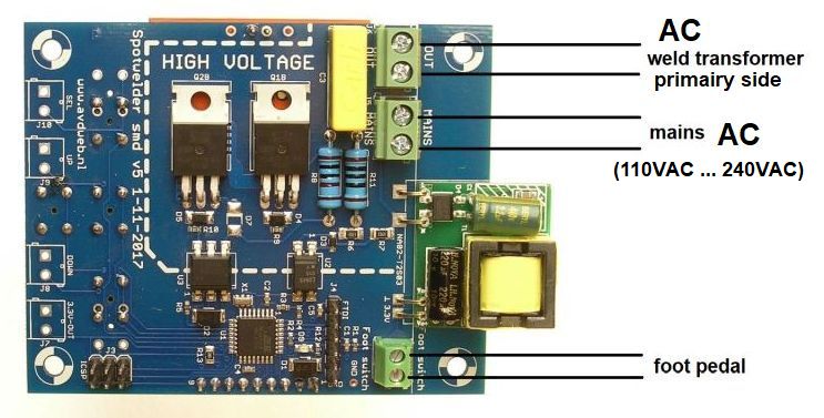
Wiring and mounting
No connectors are required, because screw terminal blocks are used.
Note: the in and output connectors are for AC voltage and there is no + or -.
 Spot welding pulse timer controller wiring
- MAINS: 110VAC to 240VAC input
- OUT: output to the welding transformer
- Footswitch (optinionally)
Optional:
- 3.3V-out: optionally output
- SEL: optionally external switch connection
- UP: optionally external switch connection
- DOWN: optionally external switch connection
Weld times
The time-table has a logarithmic distribution. The distance between the steps is 20% to 30%:
0, 10, 20, 30, 40, 50, 60, 80, 100, 120, 150, 200, 250, 300, 400, 500, 600, 800, 1000ms.
The welding times are different for 60Hz mains: 8.3, 16.7, 25.0, 33.3, 41.7, 50.0, 66.7ms etc. But because these are not round numbers, the fictional weld times for 50Hz are still used for 60Hz. So at 60Hz, a welding time of 1s is actually 830ms.
- Pre-weld time: 0ms to 1000ms
- Weld pause time: 0ms to 1000ms
- Weld time: 0ms to 1000ms
To protect the microwave oven transformer, the maximum welding time is 1s. For longer welding times, use the continuous mode.
Here are some oscilloscope images of the measured weld current:
 Weld current for weld time 10ms
 Weld current for weld time 20ms
 Weld current for weld time 30ms
Heatsink
Note that the thyristors are not cooled. The reason is that the controller is used mostly for welding nickel tabs on batteries where the welding time is maximal 250ms. With this short welding time, the thyristors do not become hot. A cooling plate makes the controller bigger and heavier and the shipping costs would exceed the costs of the controller.
There is another reason: the controller is used mostly in combination with a transformer from a microwave oven (MOT). The MOT is not designed for welding and is quickly overheated so that long welding times are not allowed. In practice, the MOT is overheated much faster than the thyristors.
Interval time
We also have to take into account the minimum interval time between successive welds. The MOT and the thyristors need some time to cool down. When we weld batteries manually, the electrodes must be accurately moved from one weld to another each time, this ensures sufficient interval time.
Practical welding examples
The thyristors do not get too warm at a total welding time, including pre-weld, of 500ms and a time between the successive welds of 10s. But the MOT and the welding cables will then become already very hot. With a welding time of 250ms and an interval time of 10s, no parts get too hot.
Controlling high-power spot-welding machines
The controller can be used also for professional, high-power spot-welding machines. The thyristors must then be replaced by larger ones. But here, longer welding times are common, up to 3s. The thyristors may get too hot when using long welding times with short intervals. You have to use a heatsink when the thyristors get to warm. Pay attention to electrical safety when mounting a heatsink! Check the temperature of the thyristors after the voltage has been removed.
Open-source software
There are no secrets, the advantage of this spot welder is that the software is open-source unlike other controllers.
Download the software at Github
Because the software is open source, it can be customized. If you have an idea how to improve it, please let me know. Then I will implement it and add to Github. You can read here how to update the software yourself with the Arduino IDE.
To re-program the spot welder you need this:
FTDI Basic Program Downloader Module
For sale on eBay for €2.50 including shipping.
Built-in power supply
The controller contains a mains power supply and works on all mains voltages worldwide from 110V to 240VAC, 50 and 60Hz. You only need an extra microwave transformer.
How to customize weld times
You can change the weld-times yourself in the Arduino sketch, which you can download at GitHub. The weld times are in this section:
int preweldTimeValues[]={10, 20, 30, 40, 50, 60, 80, 100, 120, 150, 200, 250, 300, 400, 500, 600, 800, 1000};
MenuItem preweldTimeItem = MenuItem("Preweld, ms", UpDownValueTable(4, preweldTimeValues, arrayLenght(preweldTimeValues))); // valuesPtr, table, arrayLenght

int pauseTimeValues[]={10, 20, 30, 40, 50, 60, 80, 100, 120, 150, 200, 250, 300, 400, 500, 600, 800, 1000};
MenuItem pauseTimeItem = MenuItem("Pause, ms", UpDownValueTable(14, pauseTimeValues, arrayLenght(pauseTimeValues)));

int weldTimeValues[]={10, 20, 30, 40, 50, 60, 80, 100, 120, 150, 200, 250, 300, 400, 500, 600, 800, 1000};
MenuItem weldTimeItem = MenuItem("Weld time, ms", UpDownValueTable(11, weldTimeValues, arrayLenght(weldTimeValues)));
For instance, to add two weld time steps 1200ms and 1500ms, change this line:
int weldTimeValues[]={10, 20, 30, 40, 50, 60, 80, 100, 120, 150, 200, 250, 300, 400, 500, 600, 800, 1000, 1200, 1500};
Drilling the front panel
 Spotwelder controller front panel drawing
Microwave oven repair safety precautions
Working on a microwave oven is extremely dangerous. You will normally NOT survive the high voltage of 4000V, the available power of more than 1000W is enough to kill you instantly like an electric chair. Normal insulated tools are not safe, the high voltage may strike through it. Please read this article first.
The microwave oven high-voltage is 5 times as dangerous as the overhead line of a train, see the video here:
 Microwave oven repair safety precautions
Questions
If you have any questions, please post them on forum.arduino.cc.
Circuit description
Solid state relays with standard TRIACs will not work here, because the load is highly inductive. Standard TRIACs have turn-off problems with inductive loads, while SCRs always turn off at the negative half-cycle. Therefore, an antiparallel back to back connected thyristor control is used here. For controlling high inductive loads, there are currently suitable varistors available, in the new version of the spot welder that will come in a year, these will be used.
The RC snubber network R11 and C3 protects the circuit from voltage transient spikes. D1 and D2 are transient-voltage-suppression diodes (TVS) but superfluous, in the next version they are not used anymore. The FTDI connector J4 is for re-programming. The ICSP connector is for burning the Arduino bootloader.
 Spot welding pulse timer control panel with TFT display circuit
Zero crossing detector circuit
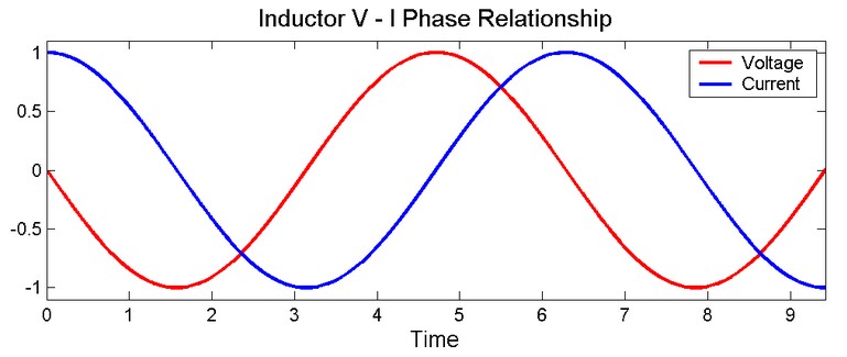
This circuit necessary for the reduction of the weld transformer inrush current, to prevent the mains fuse blow up. The current through the weld transformer, which is an inductive load, will lag behind the voltage by 90º. This is the reason that, to reduce the inrush current, the optimal switch-on time is not the zero point of the mains sinus but the top of the sinus. To be able to do this, the Arduino has to detect the mains zero crossings, this is done by U2. The delay time in the software "sinusMax_us" is 4583µs, this strange number is the average of 1/4 cycle of 50Hz and 60Hz.
Setting the power of the welding current is done only with time control and not also with current value control. At some spot welder controllers, the current value can be set too, but because this works with phase control, this will increase the inrush current with the risk of blow up the main fuse. Weld-time setting has the same effect.
High voltage!
Pay attention: the PCB is directly connected to the mains, just the low voltage part is safe. Usage is at your own risk.
Maximum thyristor current
The maximum RMS on-state current for the BT151-800R is 12A. However, for short weld times we can take the non-repetitive peak on-state current, this is 50A for weld times below 0.5s. For a normal microwave oven transformers the thyristors are adequate oversized. Take stronger thyristors if you are using a large weld transformer, e.g. the TN5015H-6T, TN5015H-6I, CMA30E1600PB, which max. RMS current is 50A and max. average current 30A.
Alternistors for high inductive loads
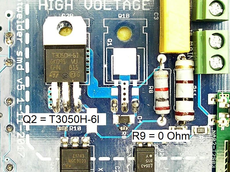
You can also use a high power alternistor instead of stronger thyristors. One alternistor replaces both thyristors, it is also cheaper.
An alternistor is a special kind of triac, different names are used:
- Snubberless triac
- Three-quadrant triac
- Alternistor
- High commutation triac
The T3050H-6I, available at Mouser, works very well. Just replace Q2 with the alternistor, remove Q1 and make R9 0 Ohm:

User guide
- Use the up, down and select button for setting the parameters, see the video on YouTube.
- The settings are stored in the EEPROM.
- Press the weld button or the foot pedal to weld.
- The LED on the back flashes continuously to indicate that the controller is working correctly.
Continuous mode:
There is a possibility to weld as long as the weld button is pressed. To enable this mode, set the welding time to 0 (*note*), press and hold down the weld button simultaneously during power on for 1 second and than release the button. Now you can weld continuously without the timer. Take care: the transformer will be overheated easily, so use this feature only for testing or for measuring the weld current.
More information
You may find some more information at the article of the old spotwelder controller.
Links


