Motor controller
Related articles
- Repairing any ebike mid-drive or hub motor electronics with an external Chinese motor controller
- S-KU63 e-bike square wave current controlled motor controller
Motor controller
Brushless DC motor animation
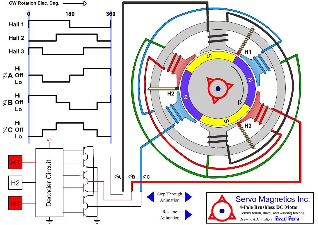 4 pole brushless DC motor animation
For motor animations, see Educypedia.
The motor current vs controller input current
A BLDC motor controller works a bit like a buck converter. Therefore, the motor current can be higher than the controllers input current.
For measuring the motor power, you can consider the motor and the controller as one unit. So, the motor power is simply Ubattery x Ibattery. The motor current itself is of no importance. Therefore, a motor controller can measure simply the input current by a single shunt.
Motor controller selection
I use a cheap ($15) and small 6-FET motor controller from China which is described here.
Motor controller links
Pedal assist sensor
In the EU, for a pedelec, motor assistance above 6kmh shall be provided only when the cyclist pedals forward. Therefore a pedelec requires a PAS (pedal assist sensor) to detect weather the rider pedals.
To meet the regulations, the motor controller must behave as follows:
- Pedalling forward with using throttle → motor ON. Motor speed depends on throttle or speed switch. Max speed 25kmh.
- Pedalling forward without using throttle → motor OFF
- Using throttle without pedalling forward → motor OFF
- Speed < 6kmh and using throttle → motor ON
Pedelecs with throttle
Most pedelecs don’t have a throttle. The motor assistance starts automatically when starting pedalling. The motor power can depend on the pedal speed or pedal force. The disadvantage is that even at low speeds there is pedal assistance, which is not needed. It uses unnecessarily a lots of battery power. Assistance is just needed at hills or at wind.
At pedelecs, a throttle is allowed, it must be disabled automatically when not pedalling. At my e-bike, the pedal assistance is controlled by a three position switch. The cyclist can select maximal, medium or no assistance.
Pedelec speed & pedal legalisation device
Many Chinese motor controllers can be used without pedalling, which is not allowed for pedelecs. Here we need additional electronics that adds the extra functionality to meet the EPAC standard. I developed a pedelec legalisation device which can be built into the motor controller.
Using RC aircraft speed controllers for e-bikes
There is a category of RC speed controllers which are called "high voltage". Some of them can be powered with batteries of 12 Lithium cells in series. Under certain conditions, these can also be used for e-bikes. The advantage is that they are lightweight and powerful.
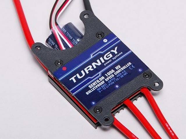 Using RC aircraft speed controllers for e-bikes
See more here: The New and Improved Brushless Electric Scooter Power System Guide
Anti spark connector
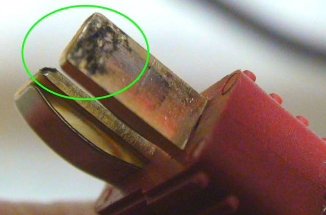
The Amass XT90S is an anti-spark connector with built-in discharge resistor.
Anti spark circuit
Connecting the battery pack creates sparks
Connecting the battery pack to the motor controller creates sparks at the battery connector because of the sudden charging of the motor controller input capacitors. The in-rush current can be greater than 100A. An anti-spark circuit is used to prevent pitting of the connector contacts. But it also prevent other components from power-up stress, such as the input capacitors.
Mechanically anti spark solution
A simple solution is to charge the capacitors inside the motor controller through a resistor of for instance 15Ω before the connectors will be plugged. The capacitor is charged in a split second and the charging current is limited, so the connector contacts will not be damaged. The anti spark resister can be mounted through a separate pre-charge cable or integrated into the connector, see here:
 Mechanically anti spark solution
Electronically anti spark solution
I use an anti spark circuit from this source. Just simply insert the connector, no sparks will occur. There is no need for a separate pre-charge cable or connector modification. The anti spark circuit can be built into the battery pack or into the motor controller.
The simple anti spark circuit requires no PCB:
Anderson Powerpole connectors are used to connect the battery to the motor controller:
Anti spark circuit built into the motor controller
The inrush current is limited to a safe value because the gate voltage rises slowly by the capacitor.
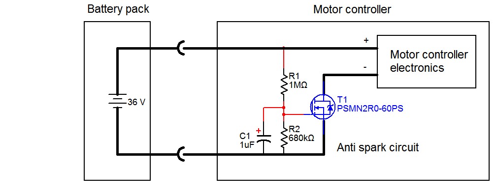


Anti spark circuit built into the battery pack
Building the anti spark circuit into the battery pack is only possible when the battery pack has a power switch. Note that in this case we need an additional battery charge input connector. The circuit can’t be used to prevent sparks from the battery charger connector. For this purpose another anti spark circuit has been developed, see here.

Note that the contact resistance of an ordinary toggle switch can be much larger than the MOSFET on-state resistance. With the anti spark circuit built into the battery pack we can eliminate the power switch in the motor current path, see here:

Eliminating power loss
The motor current flows through the power MOSFET PSMN2R0-60PS from NXP Semiconductors which has a on-state resistance of about 2mΩ. At 10A the power loss is just 0.2W, the MOSFET remains almost cold. However it is possible to prevent the power loss completely when we mount the anti spark circuit just in series with the capacitor(s) inside the motor controller.
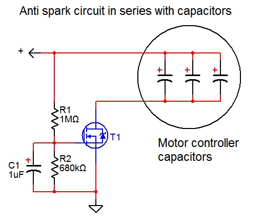 Anti spark circuit in series with capacitors
This solution requires a rigorous modification of the motor controller PCB if it contains more than one capacitor that must be switched trough the anti spark circuit.
Simple motor controller anti spark circuit
Manufacturers would do well to standard build in an anti-spark circuit into their motor controllers. Then an external anti spark circuit is no longer necessary. If a motor controller contains a microprocessor, an anti spark circuit is easy to achieve, see here:
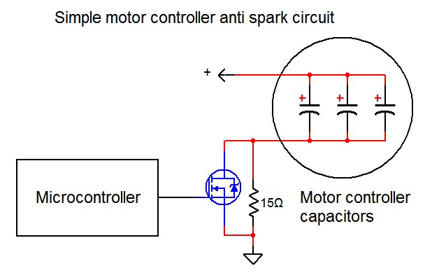 Simple motor controller anti spark circuit
Power MOSFETs
For currents above 10A use MOSFETs parallel to reduce the loss. MOSFETS TO220 with low RDS(on):
| RDS(on) [mΩ] | VDSmax [V] | ||
| PSMN2R0-60PS | 2.2 | 60 | €2.30 Mouser |
| FDP025N06 | 1.9 | 60 | |
| IRFB3006PBF | 2.1 | 60 | |
| IRFP1405 | 5.3 | 55 | |
| PSMN5R6-100PS | 4.3 | 100 | €3 Mouser |
| FDP036N10A | 3.2 | 100 | €3.75 Mouser |
The values above are for a Vgs (V gate-source) of 10V. RDS(on) can be reduced by increasing Vgs from 10V to 20V. To be sure to stay under the limit of 20V we use a Vgs of 15V.
Notes
- The circuit works well if the connector is inserted in one go. If the connector is disconnected and connected again within two seconds then sparks will occur.
- The gate voltage should be approximately 15V at nominal battery voltage. R1 = R2 * (Ubattery - 15) / 15.
- The maximum battery voltage depends on the MOSFET drain-to-source breakdown voltage.


