Measuring DC motor parameters
Related articles
- Formulas for power calculations on ebikes and hub motors
- Simulation e-bike hub / mid-drive motor efficiency vs speed
- Permanent magnet DC electric motor tuning
- Extracting motor parameters from the graph
Intro
Here we will measure the motor parameters of a 36V, 28" Cute Q-85SX hub motor, with the aim to run ebike simulations in Excel.
Motor parameters
A PM motor (permanent magnetic) can be characterized mainly by these parameters:
- Resistance R
- Motor constant k
- Friction torque Tf
Motor resistance R
 Measuring 3 phase DC motor resistance
For the copper loss, the resistance between two motor terminals is important, regardless of the delta or wye winding scheme. The resistances of the individual motor windings are not measured here. When the winding scheme is known, we may back calculate the individual motor windings. The resistances can be determined by applying a current, and measuring the voltage. One connection remains open. Than calculate R = U / I. Used is a current of 200mA, because higher currents are measured with less accuracy with some digital multimeters.
Measured is Rab = 307mΩ, Rbc = 305mΩ and Rac = 308mΩ.
Measuring the motor speed
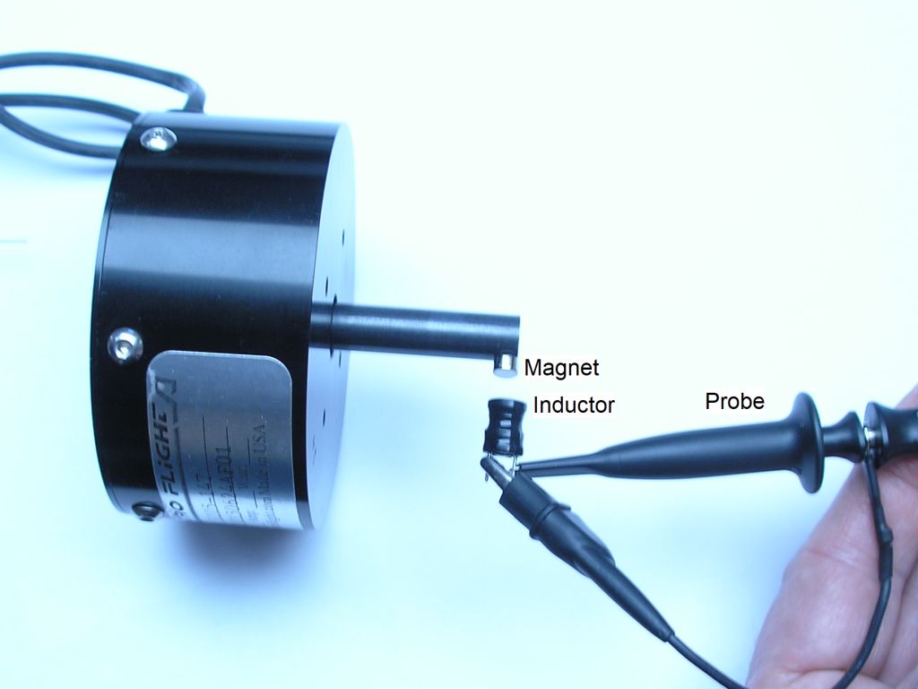
I measured the motor speed with a magnet and an oscilloscope to measure the frequency.
 Measuring motor speed with a magnet
Motor constant k
If the motor contains a gearbox, the motor constant kt relates to the motor-gearbox combination. Let the motor run at full speed without load.
Measure the voltage, no load current and rpm:
- U = 38.7V
- I0 = 0.53A (measured at U)
- rpm = 239
Calculation of k:
- k = U / ω = U * 60 / ( 2 * Π * rpm)
- k = 1.54
Friction torque Tf
- Tf = P / ω = U * I0 * 60 / ( 2 * Π * rpm)
- Tf = 0.82
Also
- Tf = I0 * k = 0.82

