Simple hub motor test stand
Intro
Motors are generally assessed on basis of their torque/speed curve. This curve can be created on basis of the motor parameters, see HERE. However, the torque/speed graph for small motors can't be calculated reliably because the mechanical losses, which are substantial, can't be written well in a formula. With the test bench, the curve is measured mechanically, which has the advantage that all effects are taken into account.
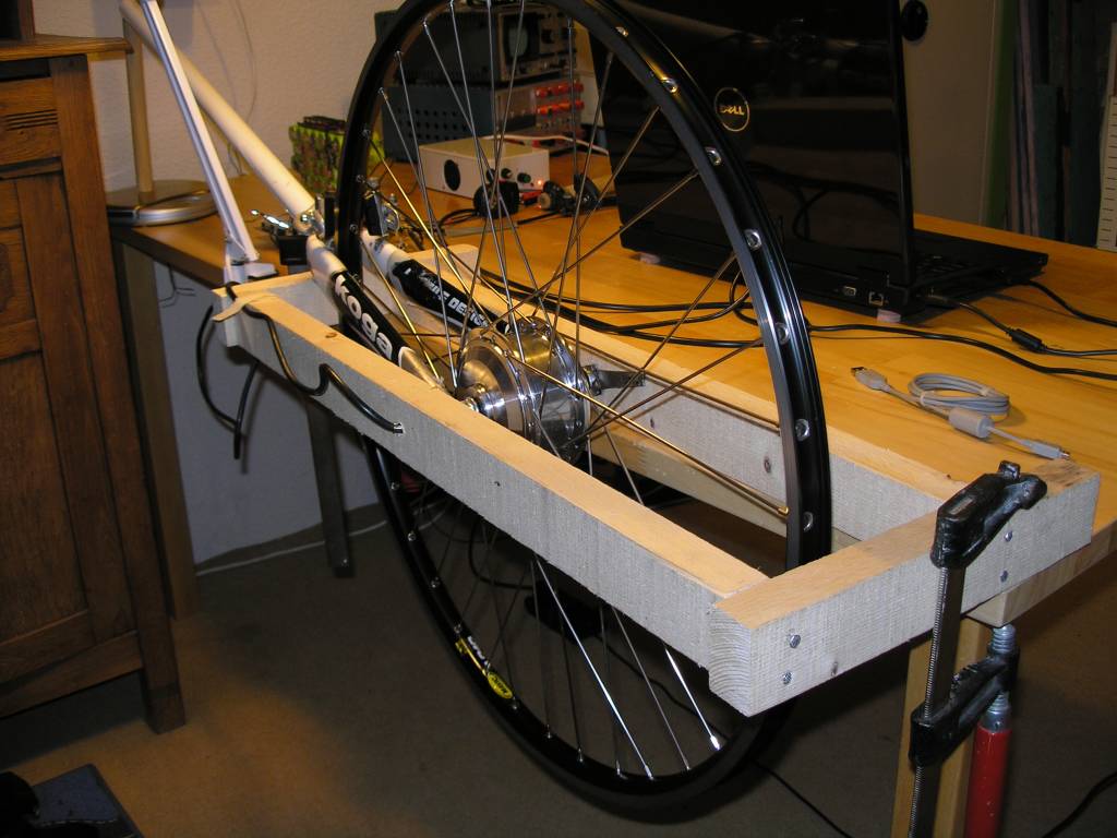
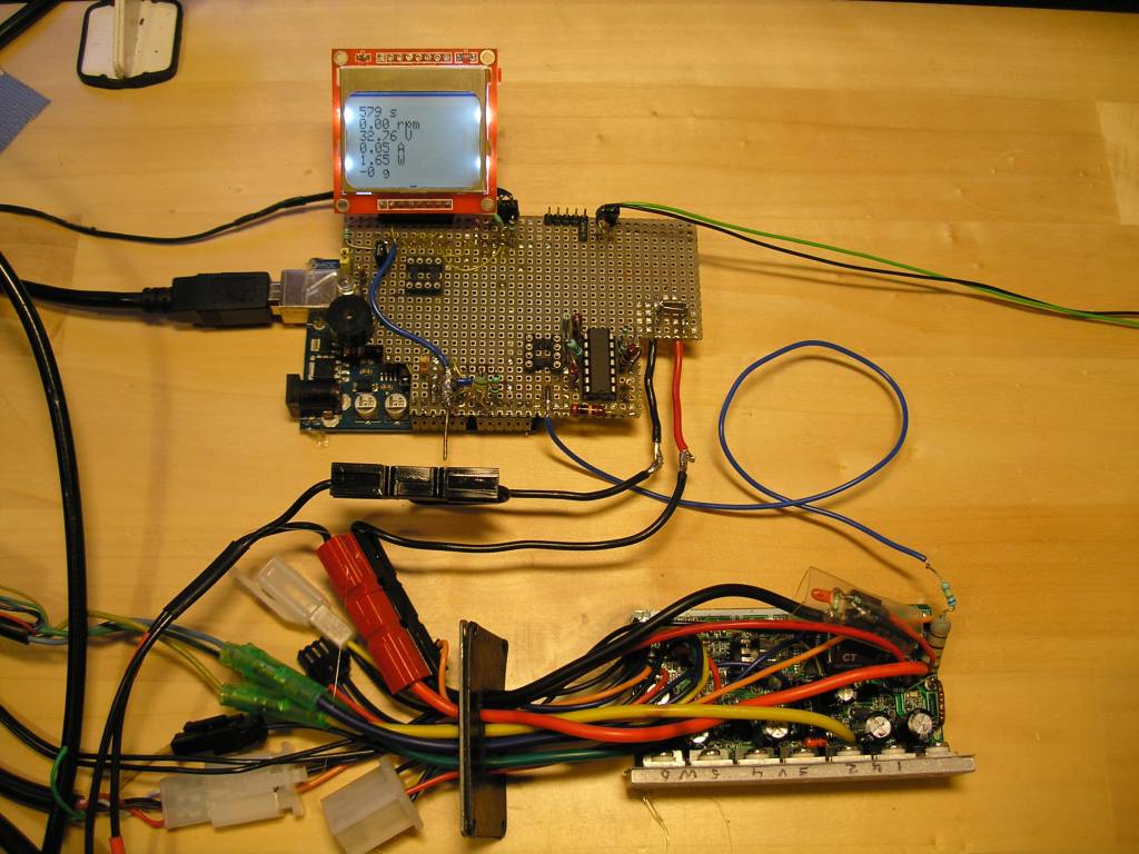
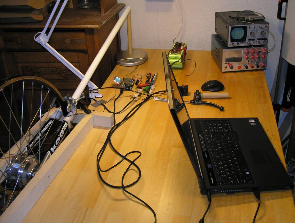
To test hub motors, I developed this motor test bench. The data of the measurements are logged with an Arduino microcontroller and sent to a laptop.
Arduino motor test stand circuit 2011
 Arduino motor test stand circuit 2011

Mechanical Notes
The front fork can rotate freely in the wooden frame.
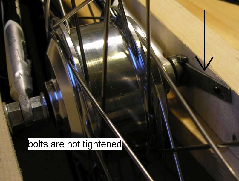
The motor shaft can rotate freely in the front fork, so the bolts of the motor shaft are not tightened to the front fork.
The motor shaft transmits its torque to the wooden frame with a torque arm.
Motor test bench electronics
Motor torque measurement
Measuring the torque (T) is done with a kitchen scale which measures the motor force (F) at a certain distance from the axis. The torque is
T = F x arm length
This method is quite accurate because the deviation of a kitchen scale is small. Moreover, the scale can be calibrated with a scale in a supermarket, which by law must be regularly calibrated. To read out the scale automatically, I use my scale Arduino interface.
Creating motor graphs in Excel
The serial output data has this format:
12 s 123 rpm 40.25 V 0.03 A 1.2 W 4 g
12 s 123 rpm 40.25 V 0.03 A 1.2 W 4 g
Copy the logged data to Excel. Use THIS Excel sheet with includes already the required formulas.
These values should be completed in the Excel sheet:
- Iq = quiescent current of the motor controller
- L = armLenght
- g = 9.812, change this for your location on earth
These are the used motor formulas in Excel:
- T = g * gram * L/1000
- Pin = P - (U * Iq)
- Pout = 0.1047 * rpm * T
- Eff = 100 * Pout / Pin
Torque/speed curve
With Excel we can create the standard torque/speed curve that is sometimes provided by manufacturers too. In this way, the performance of hub motors can be compared with each other. Unlike simulated graphs based on the motor parameters, measured graphs with the motor test bench shows also motor saturation symptoms and the impact of the motor controller.
The torque/speed itself says little about the behavior of the hub motor in practice, such as on an electric bicycle. But once we have the motor parameters, the motor can be simulated in all applications. See the article E-bike simulation.
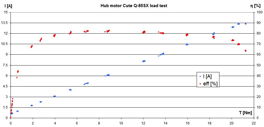 Cute Q-85SX hub motor torque/speed curve measured with my motor test bench
See for more graphs in the Cute Q-85SX hub motor test.
Test bench accuracy
The accuracy is the sum of the accuracies of all the individual measurements.
- Voltage measurement 0.5% rdg + 0.3V ~ 1.5%, calibrated with a Peaktech 2010 digital multimeter
- Current measurement 2% rdg + 50mA ~ 3%, calibrated with a Peaktech 2010 digital multimeter
- Torque measurement 0.2%, calibrated with a supermarket scale
- Wheel speed measurement 0.1%, calibrated with a stopwatch
- Arm length 0.1%
The final accuracy is thus about 5%. Note that is hard to measure the efficiency precise enough. A deviation of 5% means a lot in efficiency; for instance an efficiency of 80% can be measured as 76% to 84%. I can improve the test bench accuracy by calibrating the multimeters.
Multimeter calibration
The voltage range of multimeters can easily be calibrated yourself with 0.1% accurate voltage references and some 0.1% resistors. The 0.1% voltage references LM4040AIZ-10.0 (10V) cost about €1.60.
The current range can be calibrated by using a 5mΩ 0.1% high precision current sensing resistor such as the Vishay Y14880R00500B9R (Mouser).
Software
Download the software HERE. The following software is part of the test bench:
- Digital kitchen weighing scale interface for Arduino
- Frequency / period counter for the Arduino
- How to use the Nokia 5110 LCD Module at Arduino
- Arduino Albert library
Main program
|
#include <PCD8544.h>
#include <Streaming.h>
#include <PString.h>
#include <FreqPeriodCounter.h>
#include "Scale.h"
#include <Albert.h>
#include "WattMeter.h"
// PINS
const byte Upin = 0;
const byte Ipin = 1;
const byte wheelSpeedPin = 2;
const byte wheelInterrupt = 0; // = pin 2
const byte scalePin = 3;
const byte scaleInterrupt = 1; // = pin 3
const byte buzzerPin = 8;
// DEFINITIONS
#define wheelCircumference 2.16
#define debounceTime_ms 1 // pulse > 3ms
#define msPerSec 1023 // calibration for ATtiny
#define numberOfMagnetsPerWheel 1
#define wheelTimeOut_ms 2000
#define PiezoBuzzerFreq 2400
#define LCDupdate_ms 500
#define LCDmaxChar 100
// Compile time calculations
const float k = (float)3600 * wheelCircumference / numberOfMagnetsPerWheel; // kmh = k / period
char LCDbuffer[LCDmaxChar];
PString pString(LCDbuffer, sizeof(LCDbuffer));
PCD8544 lcd = PCD8544(10, 11, 12); // 3 pin LCD control, SCLK, DN, D/C
FreqPeriodCounter wheelSpeed(wheelSpeedPin, millis, debounceTime_ms);
WattMeter wattMeter;
Scale scale = Scale();
void setup(void)
{ Serial.begin(9600);
lcd.init(49); // contrast
lcd.clear();
tone(buzzerPin, PiezoBuzzerFreq, 20);
attachInterrupt(wheelInterrupt, wheelISR, CHANGE);
attachInterrupt(scaleInterrupt, scaleISR, CHANGE);
Serial << "Tare ";
while(!scale.tare()) Serial << ".";
Serial << " done";
}
void loop(void)
{ static unsigned long lastLCDms;
wattMeter.movingAverage();
//loopDuration_us(1, 10000);// loop = 424us
if(millis() - lastLCDms > LCDupdate_ms)
{ lastLCDms = millis();
wheelSpeed.poll();
displayLCDandScreen();
}
}
void wheelISR()
{ wheelSpeed.poll();
}
void scaleISR()
{ scale.getWeight(1);
}
|
Functions
|
inline void displayLCDandScreen()
{ pString.begin();
pString << millis()/1000 << " s\n";
//pString << kmh() << " kmh\n";
pString << rpm() << " rpm\n";
pString << wattMeter.U << " V" << (wattMeter.getUoverflow() ? "!" : " ") << "\n";
pString << wattMeter.I << " A" << (wattMeter.getIoverflow() ? "!" : " ") << "\n"; // todo endl != \n ask Mikal Hart
pString << wattMeter.P << " W\n";
pString << _FLOAT(scale.gramAverage, 0) << " g\n"; // round float, 0 decimals
lcd.clear();
lcd.print(pString);
lcd.display();
replaceChar(LCDbuffer, '\n', ' ');
Serial.println(pString);
}
inline float kmh()
{ return (float)k / wheelPeriod();
}
inline float rpm()
{ return (float)60000 / wheelPeriod();
}
inline int wheelPeriod()
{ if(wheelSpeed.elapsedTime > wheelTimeOut_ms) return 0;
else return wheelSpeed.period;
}
inline void replaceChar(char *str, const char a, const char b)
{ while(*str != '\0')
{ if (*str == a) *str = b;
str++;
}
}
bool loopDuration_us(bool doPrint, int skip)
{ static unsigned long lastLoopTime;
static int i;
unsigned long time = micros();
unsigned long loopDuration = time - lastLoopTime;
lastLoopTime = time;
if(i++ >= skip)
{ if(doPrint) Serial << " " << loopDuration << " ";
i=0;
return true;
}
return false;
}
|


