Permanent magnet DC electric motor tuning / optimization
- Related articles
- Improve motor performance by tuning
- Electric motor theory
- Brushless DC motor animation
- Brushless DC motor losses
- Motor tuning possibilities
- Stronger magnets
- Higher fill factor
- Increasing motor speed
- BLDC motor control methods
- Two stage power conversion
- Electromagnetic gearing
- Pseudo Direct Drive (PDD)
- Separated phase sectors
- Delta and wye motor winding schemes
- Motor theory links
Related articles
- Measuring DC motor parameters
- Formulas for power calculations on ebikes and hub motors
- Simulation e-bike hub / mid-drive motor efficiency vs speed
- Extracting motor parameters from the graph
Improve motor performance by tuning
This article deals particularly about e-bike hub motors, but is also applicable to permanent magnet and brushless DC motors (BLDC) motors in general.
The fact that often motors are produced cheap, means that the motor performance can further be improved by using better, more expensive, materials. There is also made little effort to let ebike hub motors be lightweight, this could be improved also. Here we examine how we can improve permanent magnet DC electric motors.
 BLDC motor tuning / optimization
Electric motor theory
Here is a site from Physclips with theory and animations about among others electric motors:
 Electric motor theory with animations from Physclips
Brushless DC motor animation
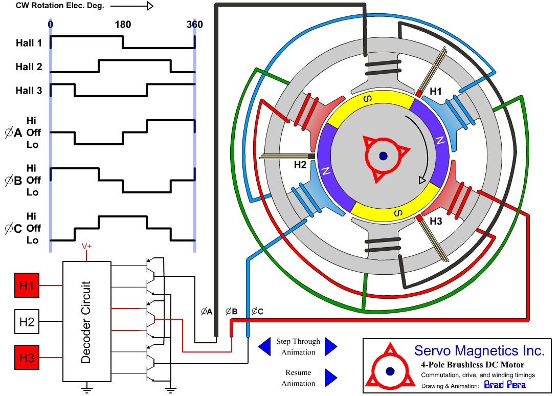 4 pole brushless DC motor animation
For motor animations, see Educypedia.
Brushless DC motor losses
The power loss dependencies are:
Electrical losses
- Copper loss ~ I2
The skin effect can be neglected for bicycle hub motors. - Transistor losses
The motor controller losses are very small by using MOSFETs with an on-state resistance of 5 or 10mΩ.
Mechanical losses
- Bearing loss ~ n (some use ~ n2)
- Windage loss ~ n3
- Gearbox loss ~ T * n
A planetary gearbox has a power loss of about 3% per stage.
Iron loss / core losses
- Hysteresis losses ~ n
- Stray load loss ~ I3
- Eddy current loss ~ n
Reduced by using laminations.
Motor tuning possibilities
Tunable motor variables
Tuning an existing (hub) motor can be done by changing these motor variables:
- Using stronger magnets. B is the magnetic field improvement = new magnetic field / old magnetic field.
- Improve the fill factor. FF is the fill factor improvement = new fill factor / old fill factor.
- Increasing the motor speed with the gear ratio. GR is the gear ratio improvement = new gear ratio / old gear ratio.
As we shall see, changing the number of windings W has no effect on the motor performance.
For tuning an electric motor it is important to know what the profit is that can be achieved by changing a motor variable so we can determine in advance whether it makes sense.
Other motor tuning ways
- Improve the motorcontroller by using a two stage power conversion.
- Changing the electromagnetic gearing.
- Improve the armature winding arrangement using Separated Phase Sectors (SPS).
- Changing the motor winding scheme.
- Carry out improvements that the manufacturer cannot implement because of patent infringement.
Stronger magnets
Neodymium magnets
Hub motors use neodymium magnets, they are currently the most powerful magnets available. A sintered Nd2Fe14B neodymium magnet has a remanence of 1 - 1.5 Tesla. Note that neodymium magnets are patented and licensed by patent holders.
Neodymium magnets are graded; N28, N35, N40 etc. The higher the grade, the stronger the magnet. The highest grade of neodymium magnet currently available is N52.
 BLDC motor tuning / optimization
Deriving the relationships
The formulas can be derived easily. The copper loss and friction loss are the two major motor losses. The other losses are ignored in order to keep it simple. Because the motor speed does not change here, we assume that the friction loss is constant, even though this is not entirely true because it depends on the magnetic field.
The back EMF constant (k) is proportional to the magnetic field B and the number of windings W:
- k = k' * W * B
- i = T / k
- i = T / k * W * B a)
By doubling the number of windings, the wire length is 2 x larger and the cross-sectional area is 2 x smaller. So R = R' * W2. The resistance is inversely proportional to the fill factor. So R = R' / FF.
- R = R' * W2 / FF b)
- Pcu = i2 * R
- Fill in a and b: Pcu = T2 * R* W2 / (k2 * W2 * B2 * FF)
- Pcu = T2 * R / (k2 * B2 * FF)
- Pcu ~ 1 / B2
W is lacking in the formula. So, the number of windings has no effect on the motor performace or loss. It only determines the motor voltage and current.
Summary
- The use of stronger magnets brings a lot because the magnetic field influence is quadratically.
- Due to the small price difference between the strongest magnets (grade N52) and the weaker ones, probably no more than 10% profit can be achieved in the magnetic field.
- The profit will be limited by the additional friction loss due to increased field strength.
Higher fill factor
Deriving the relationships
The formulas are already derived above. The fill factor formula is:
- Pcu ~ 1 / FF
Summary
- By carefully winding a motor by hand, sometimes a higher fill factor can be achieved.
Here is an example of a motor rewinding:
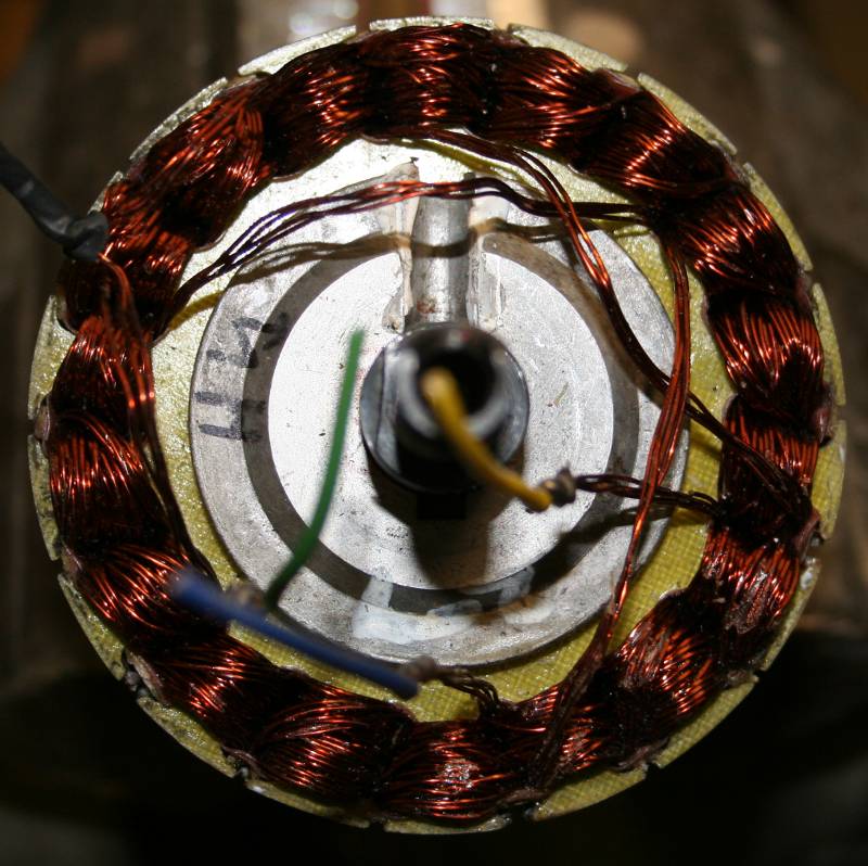 Hub motor before rewinding
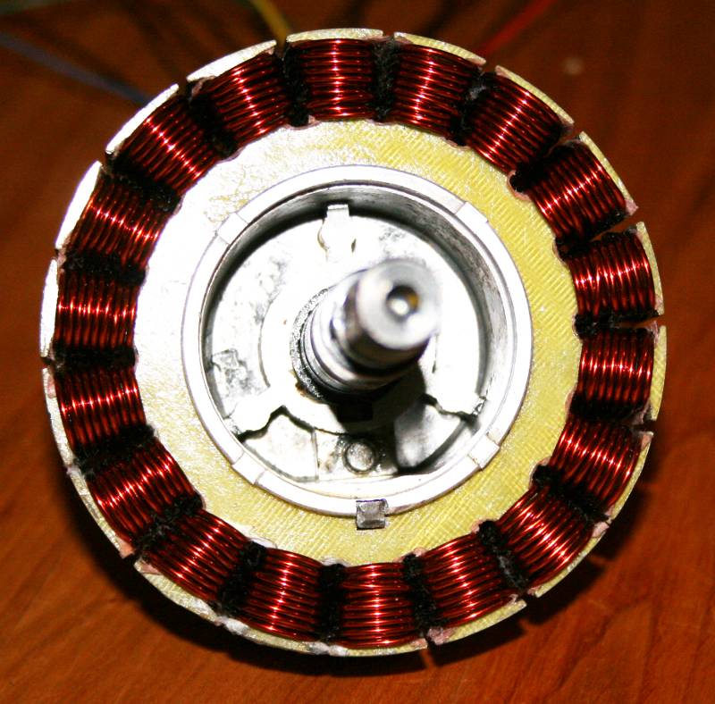 Hub motor after rewinding
Increasing motor speed
Deriving the relationship
For determining the gear ratio influence on the motor power loss, both the copper loss and friction loss must be taken in account. The copper loss depends solely on the motor current and motor torque. The motor torque will be reduced by the gear ratio:
- T' = T / GR
- i = T' / k
- i = T / (k * GR)
- Pcu = i2 * R
- Pcu = T2 * R / (k2 * GR2)
- Pcu ~ 1 / GR2 c)
- Pcu ~ 1 / n2
Due to the friction losses, the relationships in practice is are approximately:
- Pcu ~ 1 / GR
- Pcu ~ 1 / n
The friction loss is the sum of different loss factors, each with their own relationships. The deriving of the formulas falls outside the scope of this article.
- Friction loss = bearing loss + core loss
- Core loss = hysteresis loss + Eddy current loss
- Hysteresis loss ~ n and ~ B2 (1.5 ... 2.5)
- Eddy current loss ~ n2 and ~ B2
- Cogging torque. This comes from the interaction between the permanent magnets and the rotor or stator slots. It plays no role because it doesn’t consume power.
A motor designed for a specific speed can’t simply operate at a higher speed. The friction loss will become so high that the reduction of the copper loss will be superseded. In the hub motor simulation Excel sheet we can test this phenomenon.
Avoiding the larger friction loss at higher speed can only be achieved by replacing the motor by another type that is designed for higher speed. A motor with a higher speed is differently dimensioned and has a lower friction loss. An additional problem is the (planetary) gearbox loss of around 3% per stage. This must also be taken in account. Due to the many factors that are playing a role it is difficult to express the friction loss in a formula.
Summary
-
The performance of an existing hub motor can not be improved by simply increase the speed by change the gear ratio. At a certain speed, the friction loss will be dominate.
BLDC motor control methods
These are the BLDC motor control methods ranked according to complexity:
- Vector control also called field oriented control
- Sinusoidal control
- Trapezoidal control
See HERE for an extensive description. A complex motor control may give a higher motor efficiency; however, Johan Astrom has done simulations which shows just a marginal efficiency improvement for a 375W motor.
Two stage power conversion
The motor voltage is controlled by pulse width modulation. In the vast majority of brushless motor controllers, the pulse width modulation and commutation are done by the same transistors. The high PWM frequency gives hysteresis losses in the motor. Electric motors use iron cores which have large hysteresis losses, in contrast to ferrite cores. Switching power supplies therefore use ferrite cores. In a two stage power conversion a separate switching power supply is used, so the motor is spared from the high switching frequency. In the circuit below, Q1 and Q2 form part of the switching power supply.
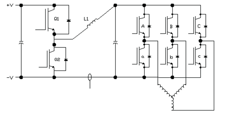 Brushless motor controller with two stage power conversion
Electromagnetic gearing
In the absence of an official name, I introduce the name electromagnetic gearing. The number of permanent magnets in the rotor does not match the number of stator poles. The difference between the number of magnet poles and the number of stator poles provides an effect that can be understood as similar to planetary gearing. The number of magnet poles divided by 2 gives the ratio of magnetic field rotation speed to motor rotation speed. Consequently the advance of the electromagnetic impulse around the motor axis proceeds much faster than the rotor turns. With more magnet poles the maximum torque is increased, while the speed of rotor advance is decreased in proportion to the ratio of magnet poles to stator poles. See more about this subject in Wikipedia.
However, a change in the number of magnets or stator poles is hardly feasible with an existing Motor.
Pseudo Direct Drive (PDD)
Magnomatics has recently invented a revolutionary Pseudo Direct Drive (PDD). This is a BLDC motor with integrated magnetic gear, which has many advantages:
Separated phase sectors
This is another way to perform electromagnetic gearing. In a separated phase sectors (SPS) motor winding scheme every second slot is only wired. SPS is a technique that allows creating slowly rotating brushless motors without using a gear. Here are some articles about SPS:
 Motor winding arrangement with separated phase sectors (Torquemax)
Delta and wye motor winding schemes
As we can see at the motor animations, there are always two windings powered and the opposite winding is not powered. The wye, star or Y configuration is the most logical because the unused winding can be left open. In the delta configuration the unused winding is powered too but generates no torque, just waste energy. Thus the wye configuration is the most efficient. The above does not apply to three-phase AC motors because here all three windings are used simultaneously with sinusoidal voltages.
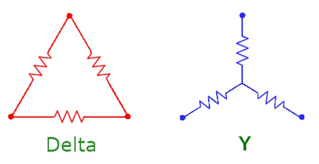 Delta and wye connected winding
Hub motor simulation Excel sheet
In the hub motor simulation Excel sheet we can also fill in the variables discussed above; W, FF, B and GR. The formulas are derived as follows:
- i = (Tout + Tf) / k
- n = 60 / (2 * π ) * { U / k - (T + Tf) * R / k2 }
- i = T / k * W * B d)
- R = R' * W2 / FF e)
- Fill in d and e: n = 60 / (2 * π ) * { U / ( k * W * B) - (T + Tf) * R / (k2 * B2 * FF }
- i = (Tout + Tf) / ( k * W * B)
You can simulate an ebike with a hub motor and look what happens if you change a variable, such as GR.


